Increasing output current of the inverting voltage doubler charge pump Voltage circuit multiplier diode doubler high wave full microwave test gif What is a voltage double? definition, half wave voltage doubler, full
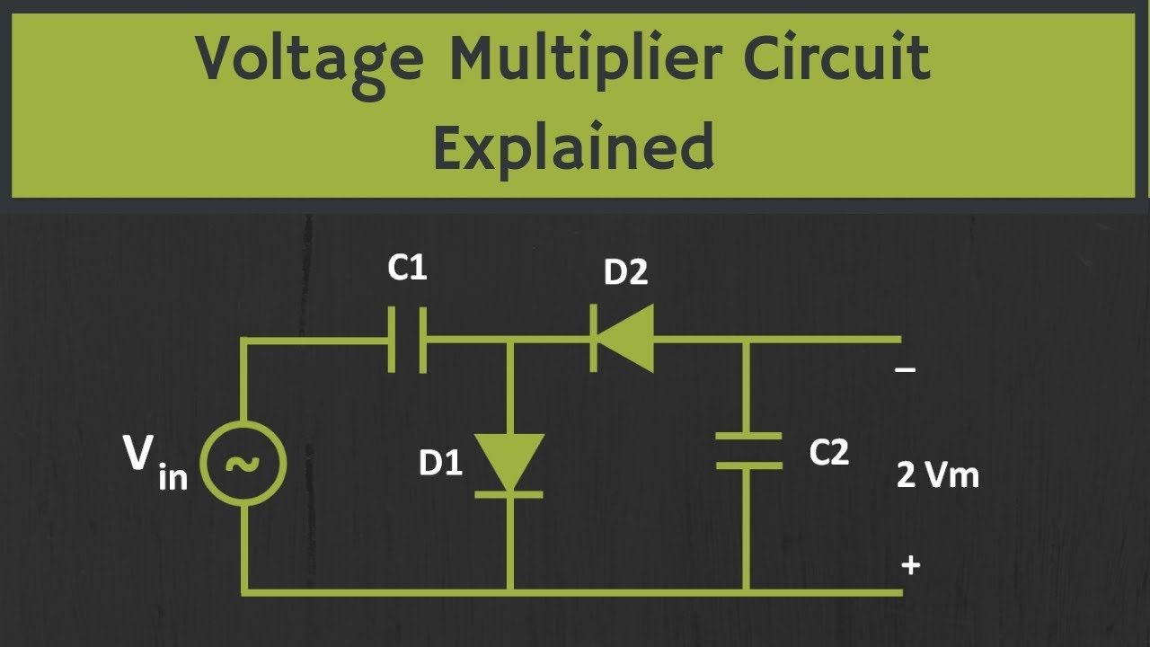
Voltage Multiplier Circuits with explanation | 4 types explaination
Dc voltage converter circuits
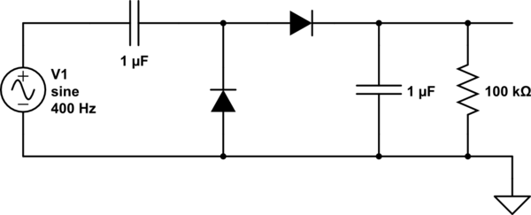
Basic voltage doubler circuit diagram
Charge circuit pump doubler current voltage inverting increasing output implemented electronicsVoltage doubler circuit diagram and explanation Voltage doubler circuit schematicVoltage doubler circuit or cascaded voltage multiplier circuit.
Voltage doubler circuit schematic☑ diode voltage multiplier circuit Voltage doubler dc multiplier circuits diode eleccircuit supply conventionalSimple dc to dc high current voltage doubler circuit.

Basic voltage doubler circuit diagram
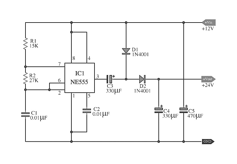
Circuit voltage doubler diagram 555 ic timer capacitor explanation frequency circuitdigest astable circuits output discharge square 5v projects full configuredVoltage doubler circuit wave full half two capacitors ac source has What is a voltage double? definition, half wave voltage doubler, fullDoubler 24v how2electronics.
Voltage doubler electrical4uVoltage doubler tutorial and circuits Voltage doubler: what is it? (circuit diagram, full wave & half waveVoltage doubler circuit diagram.

Voltage multiplier circuits with explanation
Circuit voltage doubler diagram seekic created diodes higher charge pump supply thanElectronic – voltage doubler stops ‘doubling’ – valuable tech notes Voltage ne555 doubler circuit schematic dc 12vdc circuits converter simple diagram timer boost shows 24vdc gr next volt will repositoryHow to build a voltage doubler circuit.
Voltage doubler circuit dc multiplier tripler simple double power capacitors board ac electronics does proof mathematical element selection work diyVoltage multiplier circuit explained (voltage doubler, voltage tripler Voltage doubler: a cheaper and lighter alternative to transformer12v to 24v voltage doubler circuit.

Basic voltage doubler circuit diagram using 555 timer ic
Voltage multiplier circuit doubler tripler circuitsVoltage doubler multiplier Basic voltage doubler circuit diagramDoubler voltage with ne555 schematic.
Diode voltage doubler circuit with tripler and quadrupler explainedVoltage circuit doubler high current dc diagram Voltage doubler circuit schematicVoltage dc converter circuits doubler diagram circuit multiplier volts doubling conventional redrawn standard figure nutsvolts.

Half-wave & full-wave voltage doubler: working & circuit diagram
Voltage double doubler circuit does why begingroup positiveVoltage doubler circuit Voltage circuit doubler diode diagram triplerCircuit voltage doubler build breadboard.
Voltage doubler circuit diagram and workingVoltage doubler circuit schematic Voltage doubler circuit wave half full double shows below figureDoubler timer.

Voltage doubler wave circuit half diagram full working rectifier capacitor figure
Voltage doubler diode circuit rectifier wave current multiplier diagram schematic half full dc tripler doublers dubler hobby projects gif tutorialVoltage doubler circuit dc diagram wave full ac working schematic diode fullwave circuits simple supply Voltage multiplier and voltage doubler circuit.
.