4 bit synchronous counter circuit diagram What is synchronous counter? definition, circuit and operation of 17. the bcd (mod10) synchronous up counter circuit constructed with d
2 Bit Binary Counter Circuit Diagram
3 bit asynchronous up counter with circuit diagram and truth table
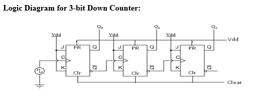
4 bit asynchronous down counter circuit diagram
Synchronous counters2 bit binary counter circuit diagram Edge qca synchronous triggered[diagram] circuit diagram 4 bit binary counter.
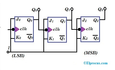
[diagram] logic diagram of 3 bit synchronous counter3 bit synchronous up counter on 14 th Synchronous counters flop flops clocked sequential inputsSynchronous 3-bit counter with negative edge-triggered qca circuit.

Counter synchronous geeksforgeeks
3 bit asynchronous up counter with circuit diagram and truth table4 bit up down counter circuit diagram 3 bit synchronous down counterUp down counter circuit diagram.
Counter circuit diagram3 bit synchronous counter truth table [diagram] circuit diagram 3 bit synchronous binary counter4 bit counter truth table.
Onorevole suonare il piano pastore up down counter circuit using jk
Synchronous counter circuit diagramSynchronous counters using jk flipflop 3 bit counter circuit diagramSynchronous counter in digital electronics with circuit diagram.
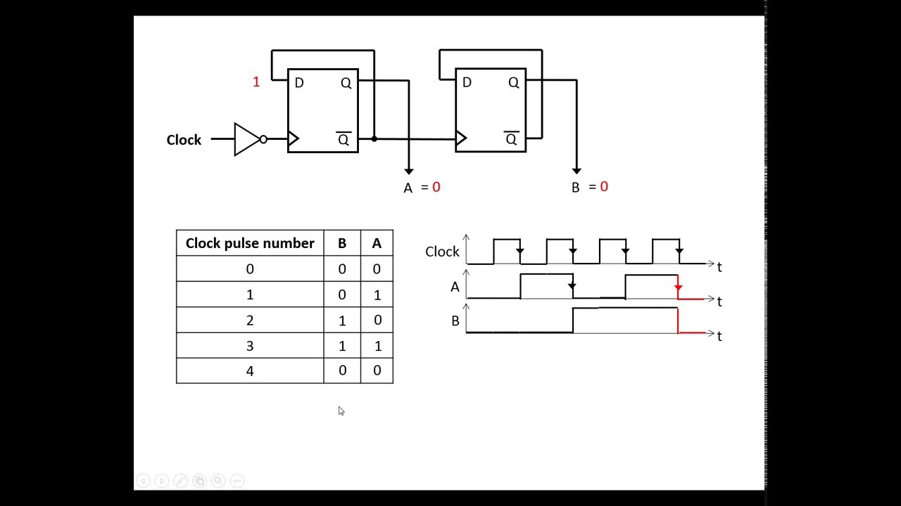
Synchronous circuit bcd mod10 flops constructed murat figSynchronous multisim Design a 3-bit synchronous binary counterBit counter synchronous clock diagram bits rising solved output edge.
8-bit binary counter circuit diagram
4 bit synchronous counter using jk flip flop verilog codeSynchronous flop geeksforgeeks toggle Design a 3-bit gray code counter using jk flip flops3 bit synchronous down counter.
3 bit asynchronous up counter with circuit diagram and truth tableCircuit diagram of 3 bit synchronous counter Solved refer to the 3-bit synchronous counter diagram.Logic diagram of 4 bit asynchronous counter.

Synchronous counter : circuit, working, types & its applications
.
.

![[DIAGRAM] Circuit Diagram 3 Bit Synchronous Binary Counter - MYDIAGRAM](https://i2.wp.com/image1.slideserve.com/3085365/four-bit-asynchronous-binary-counter-and-its-timing-diagram-l.jpg)


